
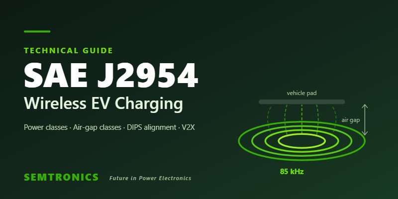
Wireless EV charging lets a driver park over a pad on the ground and charge without plugging in. Power is transferred magnetically across the air gap between a ground assembly (GA) and a vehicle assembly (VA) fitted under the car.
For this to work beyond a single manufacturer's car and pad, both sides need to follow the same rules. SAE J2954, "Wireless Power Transfer for Light-Duty Plug-in/Electric Vehicles and Alignment Methodology", is that rulebook. After earlier technical information reports and recommended practices from 2016 onwards, SAE published J2954 as a full standard in August 2024.
The standard defines power levels, operating frequency, air-gap ranges, how the vehicle finds and aligns with the pad, and how a car from one maker can charge from a pad made by another. For OEMs, charger makers and fleet operators, designing to J2954 is what turns a working prototype into a product that can be used anywhere.
Power classes and air-gap classes
J2954 groups systems by how much power they deliver and by the ground clearance of the vehicle.
| Power class | Maximum input power | Typical use |
|---|---|---|
| WPT1 | 3.7 kVA | Overnight home charging, small cars |
| WPT2 | 7.7 kVA | Home and workplace charging |
| WPT3 | 11.1 kVA | Faster home, fleet and public charging |
Higher power is being addressed separately: 22 kW light-duty systems are under development across the industry, and SAE J2954/2 is defining heavy-duty wireless charging up to 500 kW.
The vehicle pad sits at different heights depending on the car, so J2954 also defines air-gap (Z) classes. These are commonly given as Z1 (about 100–150 mm), Z2 (about 140–210 mm) and Z3 (about 170–250 mm) of ground clearance. A ground pad must transfer power across the full range of the classes it supports.
All classes operate at a nominal frequency of 85 kHz, which keeps the system clear of other radio services and allows compact, efficient magnetics.
Alignment, interoperability, efficiency and safety
Alignment. Power transfer drops quickly if the vehicle pad is not over the ground pad. The 2024 standard uses the Differential Inductive Positioning System (DIPS): the ground assembly emits a low-level magnetic field, and the vehicle measures it to work out where the pad is. This guides the driver, or an automated parking system, into position and works in rain, snow and darkness, unlike camera-based methods.
Interoperability. J2954 is written as an interoperability specification. A vehicle assembly must work with a reference ground assembly, and vice versa, so a car can charge from pads built by different suppliers. The standard also covers how the vehicle pairs with the correct pad when several are close together, as in a car park.
Efficiency. Well-designed systems reach about 90% or more grid-to-battery when aligned, and SAE cites efficiency of up to 93%. This is close to a wired on-board charger, with efficiency falling as misalignment and air gap increase.
Safety. A wireless charger has to manage stray magnetic fields for people and animals near the car, detect metal objects on the pad (which would heat up), and detect living objects in the gap. These protections are as important to certification as the power electronics themselves.
Design challenges: an engineer's view
Meeting J2954 is a system design problem, not just a coil design.
- Coils and ferrite. Coil shape, turns and ferrite layout set coupling, tolerance to misalignment and stray field. Finite element (FEM) simulation is essential before building hardware.
- Compensation networks. Resonant compensation (for example LCC or series topologies) must keep the system tuned as coupling and air gap change, without overstressing components.
- High-frequency power stage. The ground-side inverter switches at around 85 kHz at several kilowatts. Silicon carbide (SiC) devices keep losses and heat down.
- Control across the gap. Power is controlled from both sides, with fast wireless communication between ground and vehicle units, while staying stable over the full range of alignment and battery voltage.
- Thermal and EMC. Losses in coils, ferrite and capacitors must be removed, often with liquid cooling at higher power, and the whole system must meet EMC limits.
- Test. Proving efficiency, field levels and interoperability needs a lab that can run at full power with realistic loads.
Bidirectional wireless charging (V2X)
The same hardware can, with the right power stages and control, run in reverse. A bidirectional wireless system lets a parked car return energy to a home or the grid (vehicle-to-home or vehicle-to-grid) without anyone connecting a cable. This is an active area of development and a natural fit for fleets and automated parking.
How Semtronics can help
Semtronics designs wireless power transfer systems for electric vehicles. We have developed an 11 kW bidirectional V2X wireless charging prototype to SAE J2954 and are developing a 22 kW system. Our WPT lab runs power tests up to 22 kW with two 22 kW bidirectional loads, an 85 kHz high-frequency power supply and liquid cooling.
We support OEMs, charging equipment makers and engineering firms with:
- WPT feasibility studies and system specification
- Coil, ferrite and compensation design with FEM simulation
- SiC high-frequency inverter, PFC and vehicle-side DC-DC design
- Control, communication and protection design
- Prototype build and power testing
Read more about our wireless EV charging work and V2G / V2X charging, or contact our engineers to discuss your project.
